Star Delta Wiring Diagram Motor Starter
Working, construction, diagram. The star-delta wiring is an electrical circuit used in the motor power control in a three-phase power supply connection. This type of wiring connection helps in reduces the initialize high voltage in the motor windings, which helps reduce the high starting current in the starting of the three-phase induction motor.
Using StarDelta Motor Control (With Circuit Diagrams) TurboFuture
Motor terminal box showing delta connections Normally you will find a diagram on the top of the motor termination box. This shows you how to connect in star or delta. The image can be seen below:
Electrical Page StarDelta (YΔ) Motor Connection Diagram
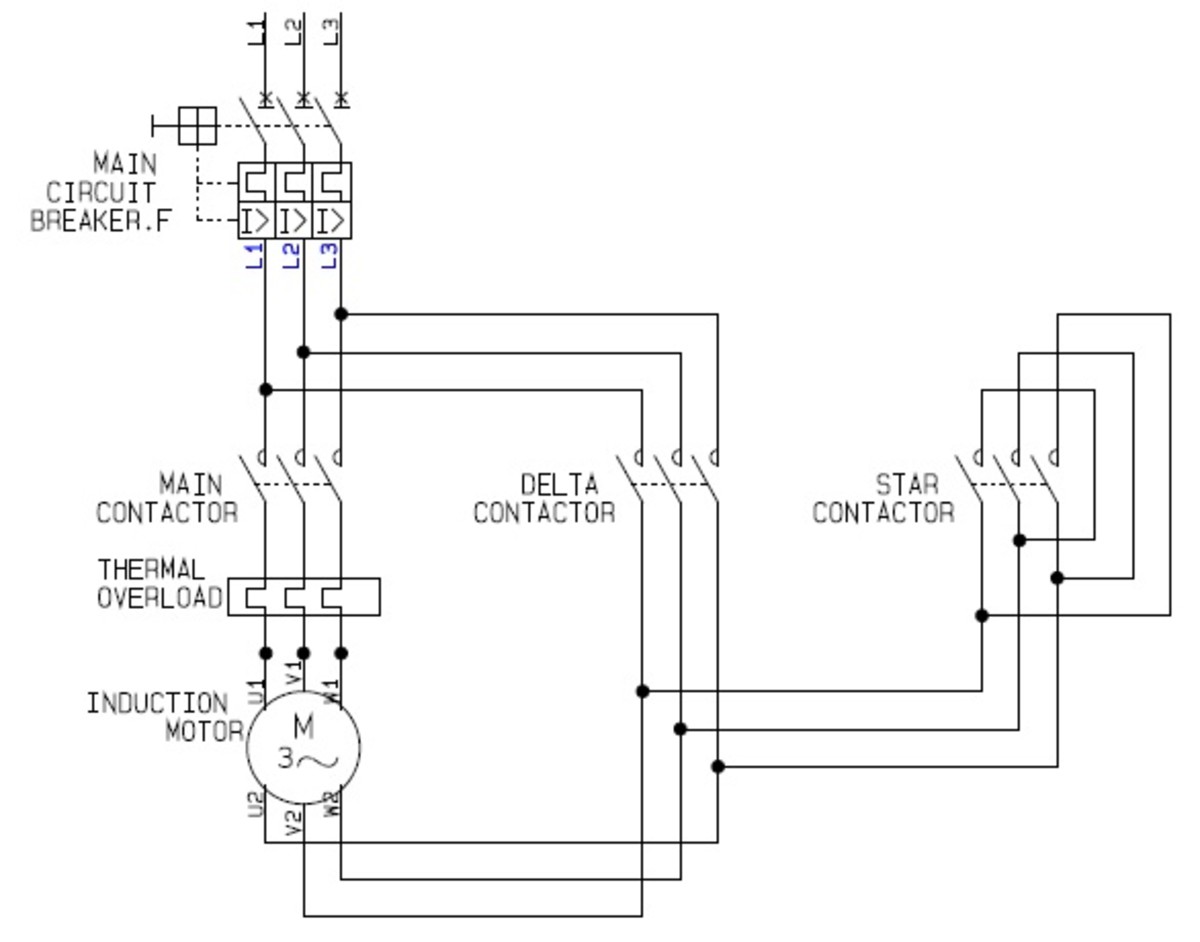
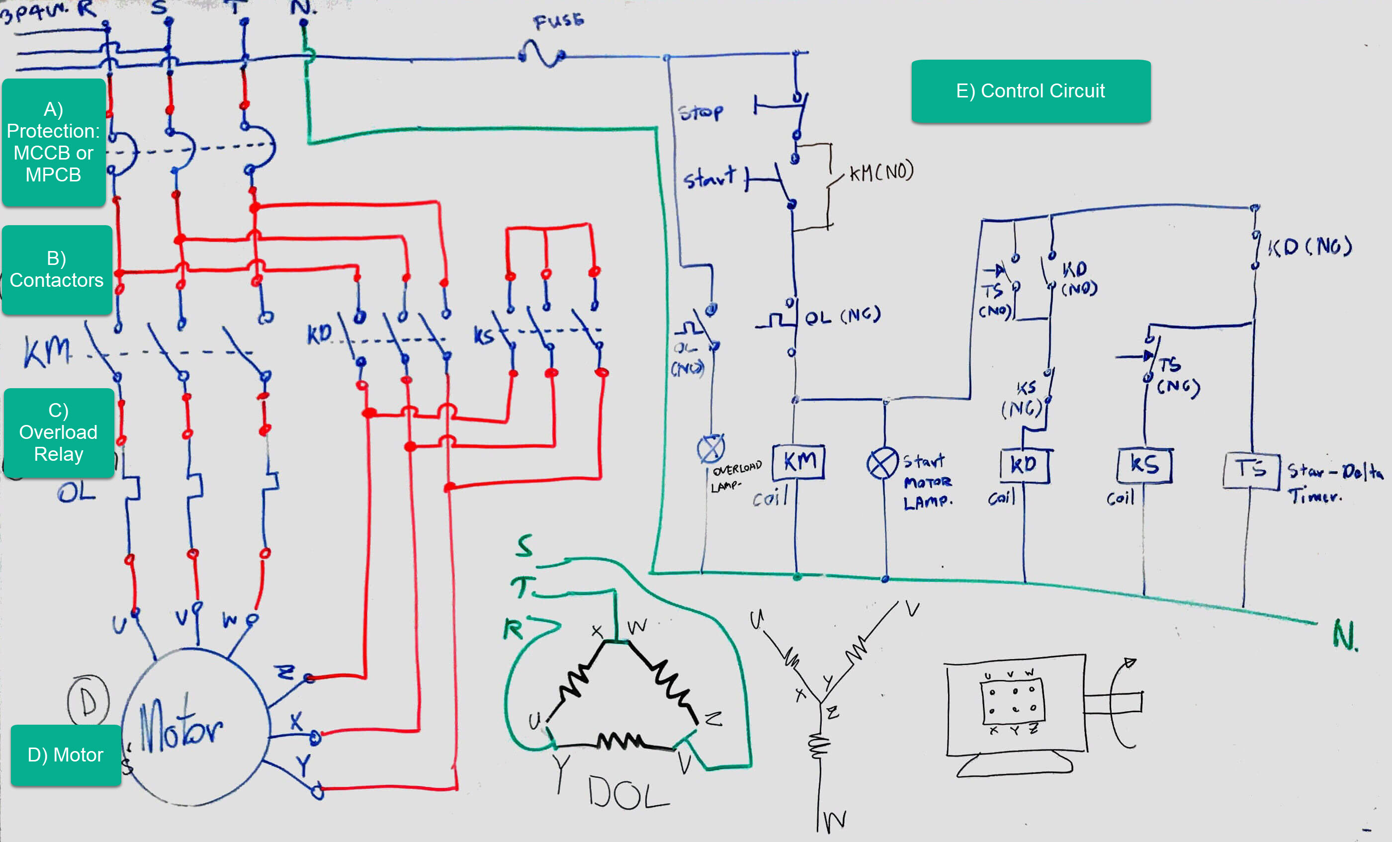
Delta connected motor internal winding terminal Safety Interlock Switches Observe carefully from the control circuit diagram the presence of interlocking contacts placed before the coils of both the star contactor and the delta contactor.
Star Delta Starter Reverse Forward Control Without Timer
0:00 / 11:08 Star Delta Starters Explained. How do star delta starters work for three phase induction motors and why do we use star delta starters. We cover the basic's o.
Wiring Diagram Of Star Delta Motor Wiring23
This is the reduced voltage starting method. Voltage reduction during star-delta starting is achieved by physically reconfiguring the motor windings as illustrated in the figure below. During starting the motor windings are connected in star configuration and this reduces the voltage across each winding 3.
Star Delta Motor Wiring Diagram Wiring Diagram Example
Delta Connection When we use Star and Delta? 3 Phase Motor Connections The 3 phases of a 3-phase winding can be connected in two different ways as per the figure shown below. Star Connection In the star connection, either the start or all the finish ends of the three windings are connected together.
Motor STAR DELTA Starter Working principle InstrumentationTools
646 25K views 3 years ago Star Delta Starter commonly use in motor to lower the inrush current upon startup of the motor. A Star Delta Starter or Y Delta Connection is the most.

Wiring Diagram Of A Star Delta Motor Home Wiring Diagram
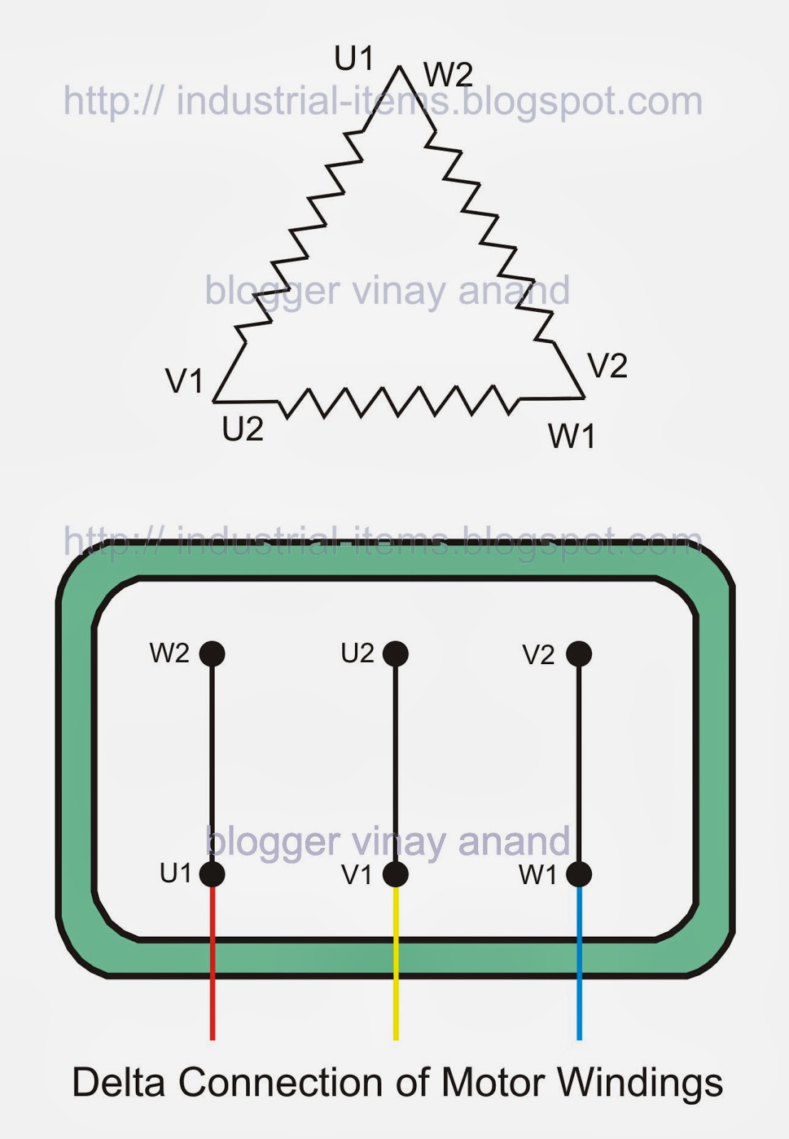
2. Delta connection. In order to make a delta connection, we connect the ends of coil U1 to the end W2, coil V1 to U2 and finally, the end of coil W1 to V2. The following image shows the delta connection scheme in an electric motor. The representation in an electrical diagram would correspond to the following image.
Star Delta Motor Wiring Diagram
A Star-Delta starter is an electromechanical device used to start and control the speed of a three-phase induction motor. This starter employs the star-delta (Y-Δ) method for starting the motor, which involves changing the motor's winding connection from a Star configuration to a Delta configuration once the motor reaches a certain speed.

GK, Current Affairs, Tutorials & Articles Star Delta Starter Theory
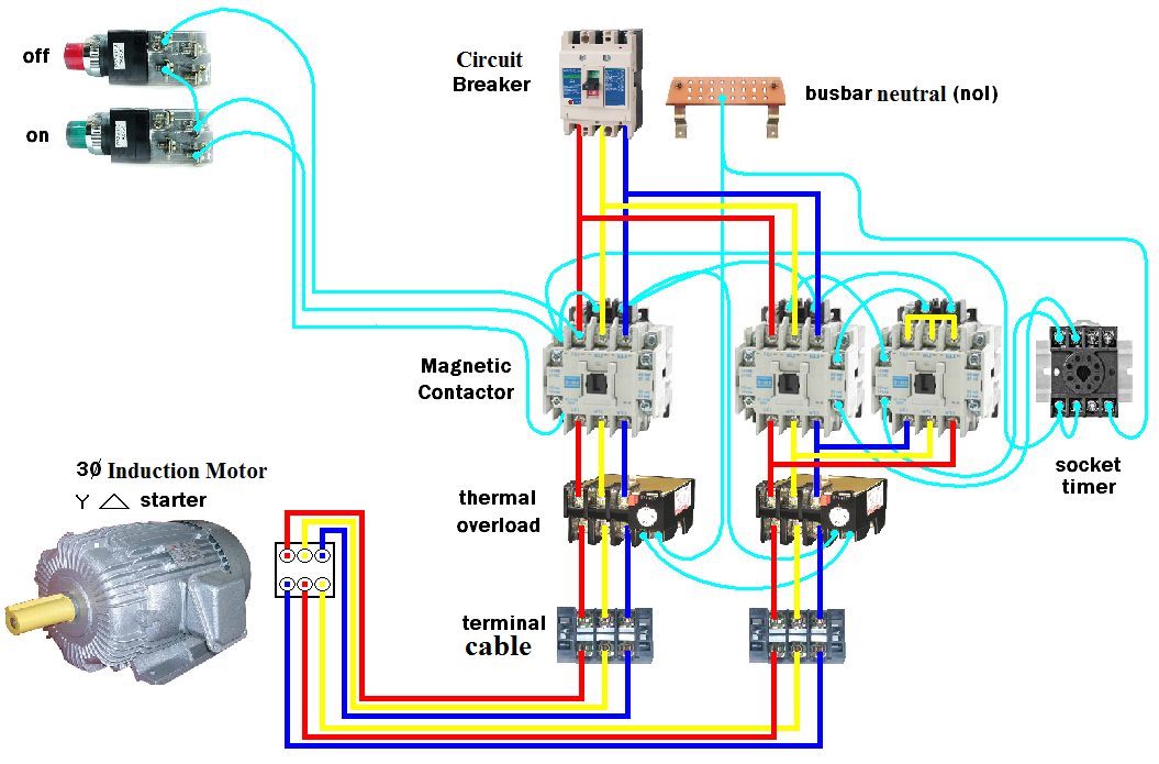
star delta starter practical Explained power wiring with diagram In this video, you will learn how to do 3 phases induction motor Power Connection in Star d.

Electric Star Delta Wiring Diagram
Delta connection of the motor Delta connection is done for high loads, in the delta connection the terminals are connected in a different way than the star connection and it is shown in the below image and we can see that the opposite ends of three coils are connected together.

3 Phase Motor Wiring Diagram Star Delta
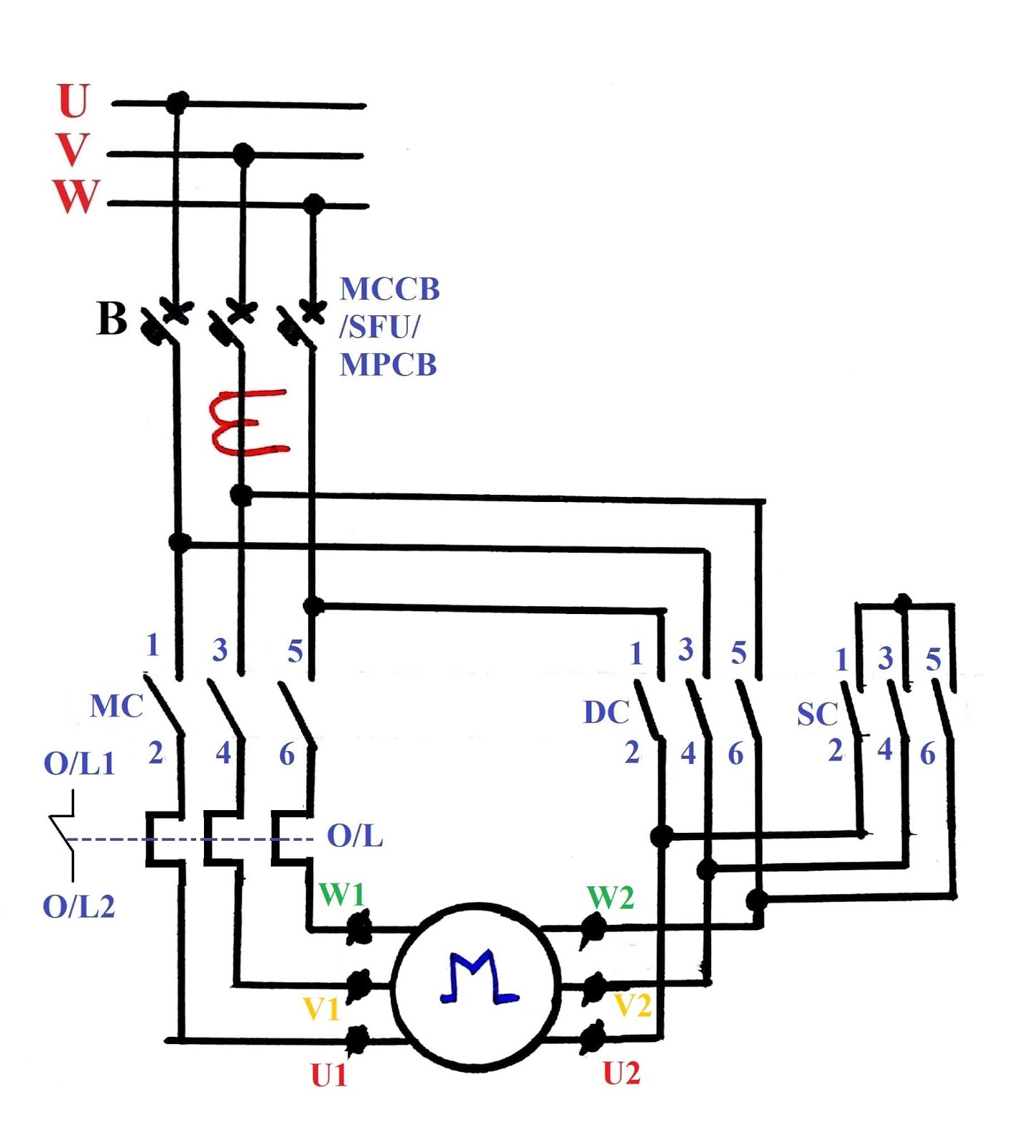
What is Star Delta connection? Star delta magic triangle When we refer to this diagram,We can see correct terminal for the winding for each phase : *CAUTION: Please refer to the name plate of motor to confirm the winding numbering ( U1,U2,V1,V2,W1,W2 ) and the motor connection of winding.

Star Delta Starter Connection Diagram and Wiring ETechnoG
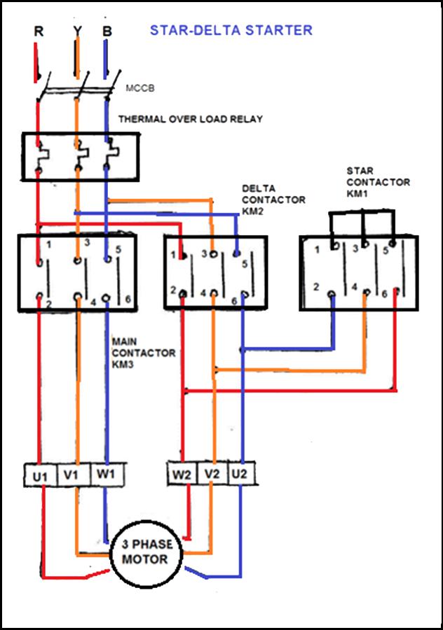
The wiring diagram for a 132kW star-delta starter used for a condenser pump is shown below: Star delta starter wiring diagram The diagram can be divided into two parts: The power circuit & control circuit. Power circuit wiring The power circuit of the starter consists of the following components:
The Beginner's Guide to Wiring a StarDelta Circuit Factomart Singapore
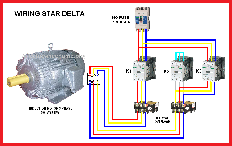
Star Delta Wiring diagram from The Motor Control Warehouse I'm going to use the old Red Yellow Blue colour coding for the phases simply because I think it's easier to see. However, we will look briefly at other colour codes later in the article. Three phase motors are used in almost every commercial and industrial building.

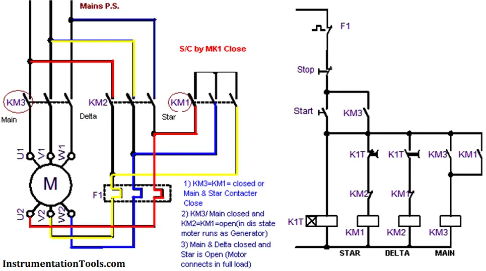
STARDELTA CONTROL DIAGRAM WITH MOTOR POWER CONNECTION
The manual control procedure for the star-delta starter without timer is relatively simple. It involves the following steps: Initial State: The motor is at rest, and the windings are disconnected. Star Connection: Press the "Start" button or close the start contactor. This connects the motor windings in a star configuration.
GK, Current Affairs, Tutorials & Articles Star Delta Starter Theory
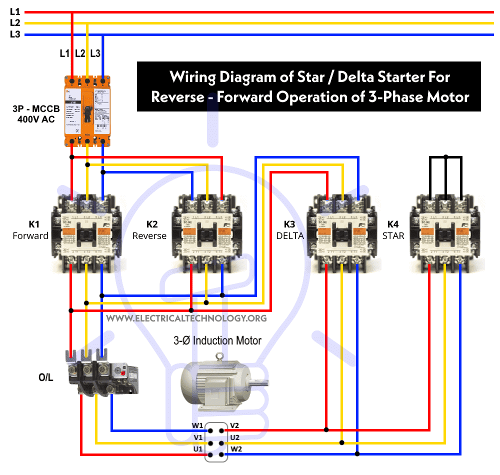
3-P MCCB is used to protect the combination of star delta and reverse / forward starter circuit from overload and short-circuit. 2-P MCB is used to protect the control circuit. The main contactor "K1" is used to operate the motor in normal i.e. forward direction. The contactor "K2" is used to runs the motor in reverse direction.